This is about a 50 lb platform that could swing freely (in all directions) from a universal joint. The platform had a smaller, less massive, pendulum hanging from it that could likewise swing freely.. but interacting with the upper pendulum either harmonically or chaotically. The lower pendulum weigh(s) could be (re)positioned along the pipe, so I could change its frequency, and experiment.
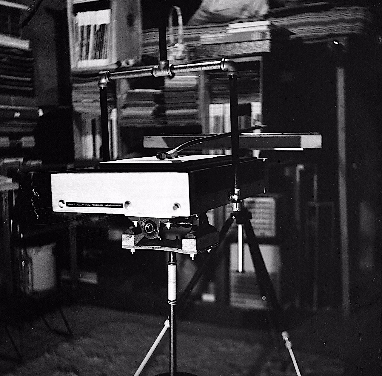
DEPH in the basement at our Millwood home, 1967.
In the middle of the photo, you see the writing platform which sat atop a sturdy wooden box holding 50 LBS of iron sash weights. Iron pipes go from the sides of the box up to the ceiling, with a U-joint fasted to the overhead floor joists. Hanging below the box/platform, you can see the lower pendulum's U-joint.
I could change the length and mass of the lower pendulum, using movable weighs of 5, 7.5, or 10 lbs.
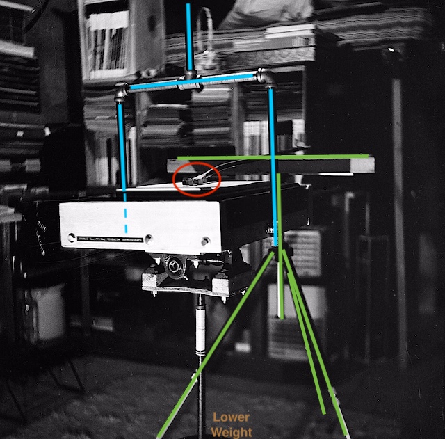
The photo shows the black camera tripod used to make the first version of pen apparatus, allowing the height of the pen arm to be adjusted during initial testing. I later built a more specialized, delicate pen. Unfortunately, the black tripod and the black pipe are aligned in the photo, so I provide an annotated photo below.
Blue: Iron Pipe; Green: Tripod; Red: Ink pen.
I learned about these machines in May 1965, from an article in Scientific American.
I (think) was a Junior in High School (~1966). As you will see, I decided to build the Double-Elliptical Pendulum Harmonograph, which took part of a year.
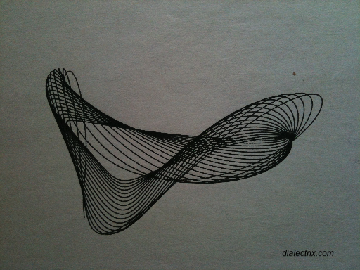
Degenerating Triangle
This harmonogram is similar to one I'd seen in the article that piqued my interest.
Getting Jazzed by the Amateur Scientist column in May 1965
In the May, 1965, the Amateur Scientist column
in Scientific American, was entitled:
Zany mechanical devices that draw figures known as harmonograms
.
The column was conducted each month by C. L. Strong, who oftentimes published descriptions of experiments conducted by readers.
Several kinds of harmonographs were described and illustrated.
I was most interested in the Double-Elliptical Pendulum Harmonograph because of the striking complexity of the patterns it could produce.
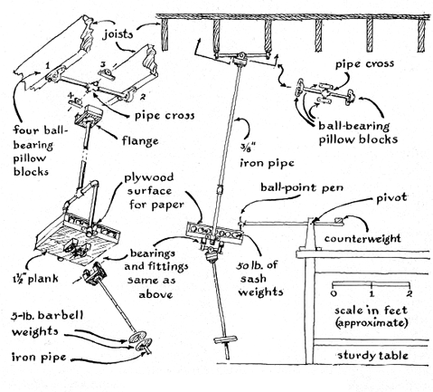
Diagram from Amateur Scientist, Scientific American, May 1965
The following is an except from a letter published in the column from a father-daughter team of Concord, Massachusetts:
Our most recent machine is a version of the elegantly simple double-elliptic pendulum first described in 1907 by British experimenters. It consists of a small wooden platform weighted with 50 pounds of iron [see illustration at lower left]. The platform is suspended through a yoke and a length of iron pipe by ball-bearing gimbals fixed to the ceiling. The figure is drawn on paper that is taped to the platform; the drawing instrument is a pen attached to one end of a counterweight level arm. This simple arrangement generates only circles, ellipses, and straight lines. The interest of these figures can be enhanced by making identical drawings and superposing one on the other with a slight displacement; moiré patterns appear.
The most astonishing increase in the versatility of the machine can be made, however, by suspending a second, less massive pendulum from the bottom of the platform, again using a gimbal arrangement. When it vibrates its own natural period, the shorter pendulum perturbs the motion of the swinging platform in an infinite number of ways. The handsomest patterns are generated when the frequency of the upper pendulum bears a whole-number ratio to that of the lower pendulum - a ratio such as 3:2 or 2:1. The adjustable factors that describe any given figure are then
the two amplitudes of the upper pendulum,
the phase angle between them,
the phase between upper and lower pendulum,
the phase and amplitudes of the lower pendulum
and the ratios of the frequencies of the upper and lower pendulums. We have scarcely begun to investigate the variety of patterns that can be generated with the double-elliptic pendulum machine.
Building the D.E.P.H and pen apparatus
I wrote to C. L. Strong in August 1966 with questions before I built mine. He replied with a full page type-written letter!
I adapted my own design from the information and illustrations in the
column, and additional generous feedback from "Red" Strong.
I designed it to just clear
the concrete basement floor in our house and to be suspended from the floor
joists overhead as shown in the column.
Finally, in March, 1967, I had iron pipe cut and threaded.
I spent $40 on eight ball-bearing pillow blocks to construct the needed U-joints.
I scavenged the 50 pounds of sash weights from Inland Metals in Spokane.
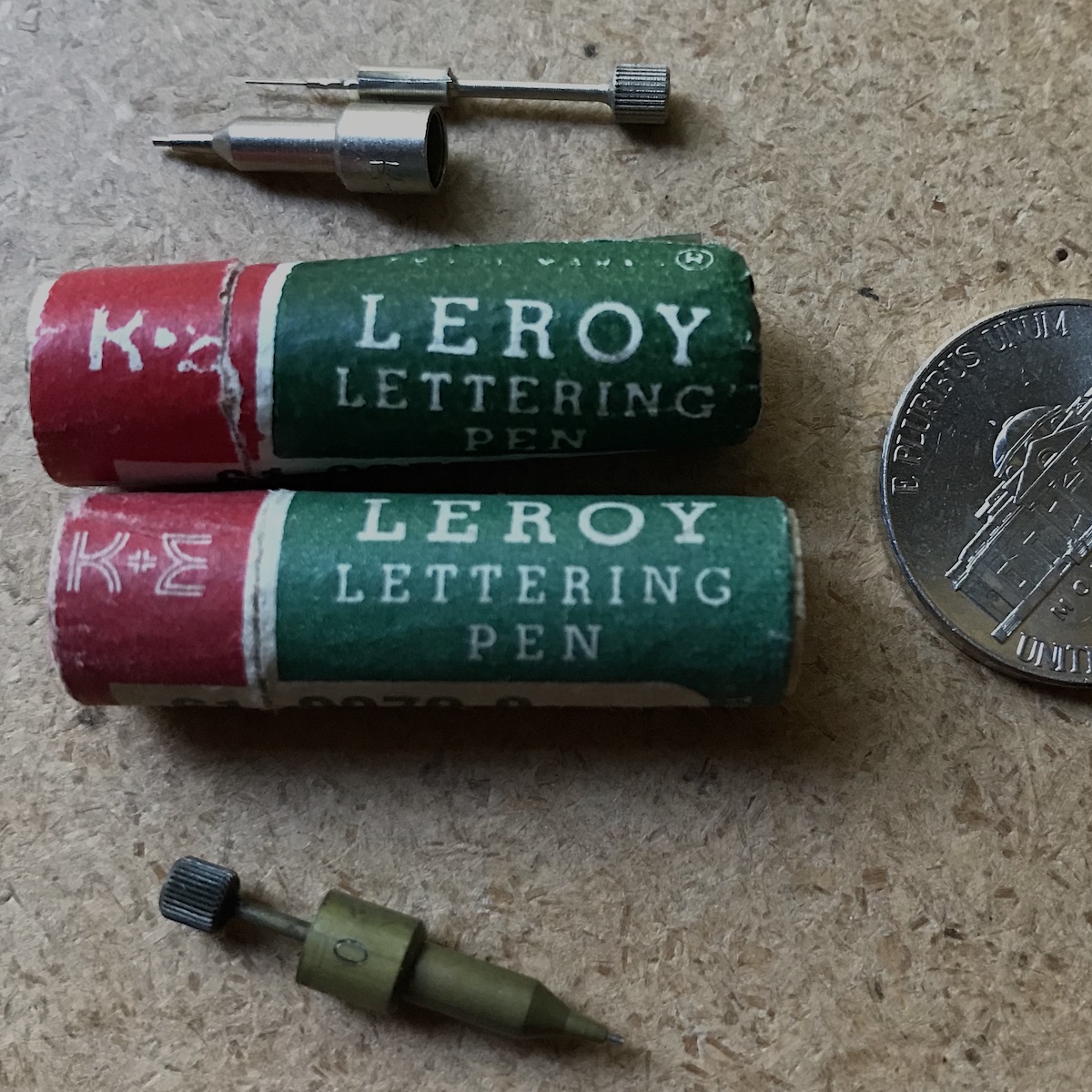
C L Strong suggested using Leroy Lettering Pens in his article. I'd never heard of such a thing, So I visited J. W. Grahams in downtown Spokane and found those. Photo below.
Leroy Lettering Pens, No. 0, and No. 1
I drew a scale drawing to figure out what lengths of pipe I needed.
I'm surprised that I don't seem to have my original plan.
It was an interesting design and construction problem because
of the way all the components related to one another, constrained by the distance between floor and joists above.
This could be an expensive project today depending on your access to
pipe-cutting and threading tools, etc.
For example, I had the ends of eight of
the pieces of pipe milled rather than threaded so that they would fit into
the bushings of the pillow blocks. I was lucky to have the old-fashioned West Valley hardware store a block way where the man often had time on his hands to do some of these things for me, with his pipe cutting and threading machine, and a nice lathe in the back room! (I rewarded him with some Harmonograms!)
Pen apparatus
After getting it built, I found that the pen apparatus was just as
important as the pendulum. I spent quite some time perfecting my
control over that design - otherwise, tracing would be botched, or the
level of friction would be too high, etc. You must be able to lower and
raise the pen gently and cleanly, the pen can't be too massive, or too light.
Because I had a lightweight counter-balance pen arm, it turned out that I
needed to add pressure by means of a delicate spring to
keep the pen from continuing upwards and leaving the paper at times, resulting in 'skips'.
(As the DEPH swings, the pen must be able to move up and down.
-- the paper is flat, and the table is swinging in a spherical section.)
The lowering, pressure-setting, and raising were all controlled by a single
lever.
To store the D.E.P.H. out of the way, I would:
remove the lower pendulum with bar bell weights and set aside
open the top of the writing platform
remove the sash weights and put them away
unscrew the upper pendulum (with platform) from the flange at the top
place the upper and lower pendulums out of the way on a special shelf
I wrote to C. L. Strong in summer 1967 with samples of my patterns. He wrote back to say they were 'Dandies"!
See my ideas page where (under Eames) I tell about visiting the Science Pavilion in Seattle, in summer 1966.
[IDEAS]
Gallery
Here are more photos of my favorite harmonograms. Each of these took just a minute or so to draw. The trick was getting the upper pendulum/platform moving well, and then to perturb the lower one just right. Then to quickly set the pen down to start the tracing.
since the upper pendulum was about 4 feet, the frequency twas about 2.5 seconds. So each of paths you see here took 2.5 seconds (not factoring in the lower pendulum, which at times was in sync with the upper pendulum, creating a longer frequency for a moment, and so on.)
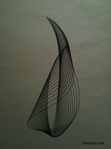
Wild Thing
Tulip
No Name
The DEPH is
currently on loan (donated?) to the Physics Department at Lewis & Clark College in Portland, Oregon. They built a new pen apparatus, a metal suspension stand, and other improvements.
It was fun to play with. It would be fun to make an updated version, with new, finer hardware.
It's always a good idea to keep a dated lab notebook or journal for such projects. I didn't, but I do have rcpts and letters that date the project. I did a series of harmonograms attempting to record the 'Variable Characteristic' as I called them.
The barbell weight(s) on the lower pendulum could be moved up and down to change the frequency of that pendulum. I glued a cloth tape measure on the pipe, and used that as a reference. I remember 7¾ was a sweet spot, and so on. I wrote the numbers on each of the test drawings.
Other Experiments before building the D.E.P.H
Before building the D.E.P.H., I experimented with some other
setups described in the column.
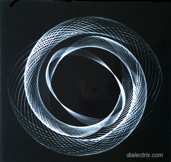
I started by taking time-lapse exposures in a darkened room
— shooting straight up at a point of
light swinging freely in orbits. The point of light was a flashlight with the glass lens taped of to a allow small square of light through. Camera: Agfa Isollette 120 B&W Film).
Since it's virtually impossible to
start a freely-suspended object swinging in a perfect circle,
the ellipse will rotate and also spiral down due to drag.
The locus of this orbit can be quiet beautiful.
The suspended flashlight might also twirl or wobble adding variation.
The 'point' of light can be a slit, making the width of the light
line vary as the flashlist orbits.
I had a darkroom, so we could shoot the film, then take it right into the developing process all in the same evening. (We didn't need to print the negative to see the basic results.) This one was made by closing the shutter for a few swings, then re-opening it to capture a few more orbits. (Actually, I think we just blocked the lens with some black paper for a moment.)
a PhotoPendulation
I should add more photo pendulations!
Twin Pendulum Harmonograph
I also experimented with a crude Twin Pendulum Harmonograph, as illustrated in the Am Sci column, using wooden dowels and such. I used the L-shaped (booze) bar in our recreation room as a platform.
But, it was limited by the fixed nature of the two perpendicular pendulums, and so produced Lissajous patterns at best..
[WikiPedia]
a Harmonogram made by a crude Twin Pendulum Harmonograph
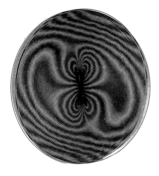
Moire Patterns
With just the upper pendulum in play, hanging from joists (Lower pendulum removed) you could get the upper pendulum going in a near circular orbit, then put the pen down. This would trace a very long spiral that could take several minutes to degenerate to a short line or point. Pen up. Having used a lot of ink, we refile the pen. Then get it orbitng again and put the pen down to draw another spiral over the first. The interaction of the spirals creates an effect reminiscent of silk patterns.
Small Moire Pattern
You'd get a more dynamic pattern if the second spiral was made orbiting in the opposite direction as the first.
Because it took so long, I typically drew smaller ones for visitors to my downstairs lair.
Good date night. LOL.
I also drew two full-page spirals separately that could be held up to light to get a moving pattern from the superimposed spirals. You get the idea.
Spokane Library 1967-68
This is a Genuine letter from 1967. I had just started at Gonzaga University, as an Off Campus commuter student, living at home the first year. These were Harmonograms that I had made in summer 1967 (and earlier).
Letter from Janet Miller - no relation.
I don't recall how I got the idea to approach the Library. I must have been aware of the art gallery there, as I did visit it when downtown.
They wanted them matted to display on the gallery wall. I submitted three or four, using double stick tape and black construction paper! Eventually, I removed them from the black paper and cut them down a bit. (I will make better scans of them for my digital archive.)
Museum of Mathematics: The Harmonograph Art of Ivan Moscovich
Temporary exhibit going on right now at MoMath.org:
LINK. Link may die! Text below copied here. I do apologize. Since many of the images appear to be copyrighted, I suggest googling for Ivan Moscovich harmonograph. I may replace this in 2022, or just remove it altogether.
From MoMath website MoMath.org:
This solo show includes almost three dozen original pieces of Ivan’s art — created using his custom-made (and patented) harmonograph — and explores the intersection of the mathematics of Lissajous curves with the aesthetics of beautiful art. Ivan fashioned the harmonograph, an analog drawing machine that uses pens and pendulums, to generate an incredible variety of elegantly swirling, multi-colored graphic configurations known as Lissajous patterns. First exhibited at the Institute of Contemporary Arts in London in 1968, the work it produced was acclaimed as the best math art of the time...
The show includes two working harmonographs for visitors to explore how the artwork is created and make their own works to take home.
See the Dialectrix Harmon-o-graph FAQ Here:
[LINK]
Difficulty of Modeling this Behavior
I may write something about this some day -- Describe the behavior intuitively, then why it isn't just two independent harmonic motions you can 'Add Up'.
The Amateur Scientist, Scientific American, May 1965, page 130.
Harmonic Curves, William F. Rigge, SJ, The Creighton
University, 1926.
Harmonic Vibrations and Vibration Figures, Joseph Goold,
Charles E. Benham, Richard Kerr and L.R. Wilberforce, edited by Herbert C.
Newton, Newton & Co., 1909.
The second two items, from The Bibliography in Am Sci were not too useful